Energy dissipation systems are often described as “a device added to the structure.” In practice, the opposite is true: first, the performance target the structure must achieve is defined, then the device that reaches that target most economically is selected. This article examines that decision chain with examples from the field.
01 Starting with the target
How much a structure will displace under earthquake loading depends not only on the stiffness of its structural system, but also on the energy it can absorb. In conventional design, this energy is handled by allowing structural members to dissipate it through damage (plastic hinging). Damper devices transfer the energy to controlled, replaceable elements — in other words, they move damage away from the structural system and into “sacrificial” devices.
That is why the decision starts with the target, not the device. In a structure such as a hospital that must remain operational after an earthquake, the target is uninterrupted use; in a warehouse, life safety may be enough. These two targets lead to completely different damping strategies.
A damper is a design choice that defines how much damage we “allow” the structure to sustain; it is not an add-on.
ProYA · Structural Design Notes02 Three device families
In practice, three main families stand out. The difference between them is what governs how they absorb energy — velocity or displacement.
Viscous (velocity-dependent) dampers
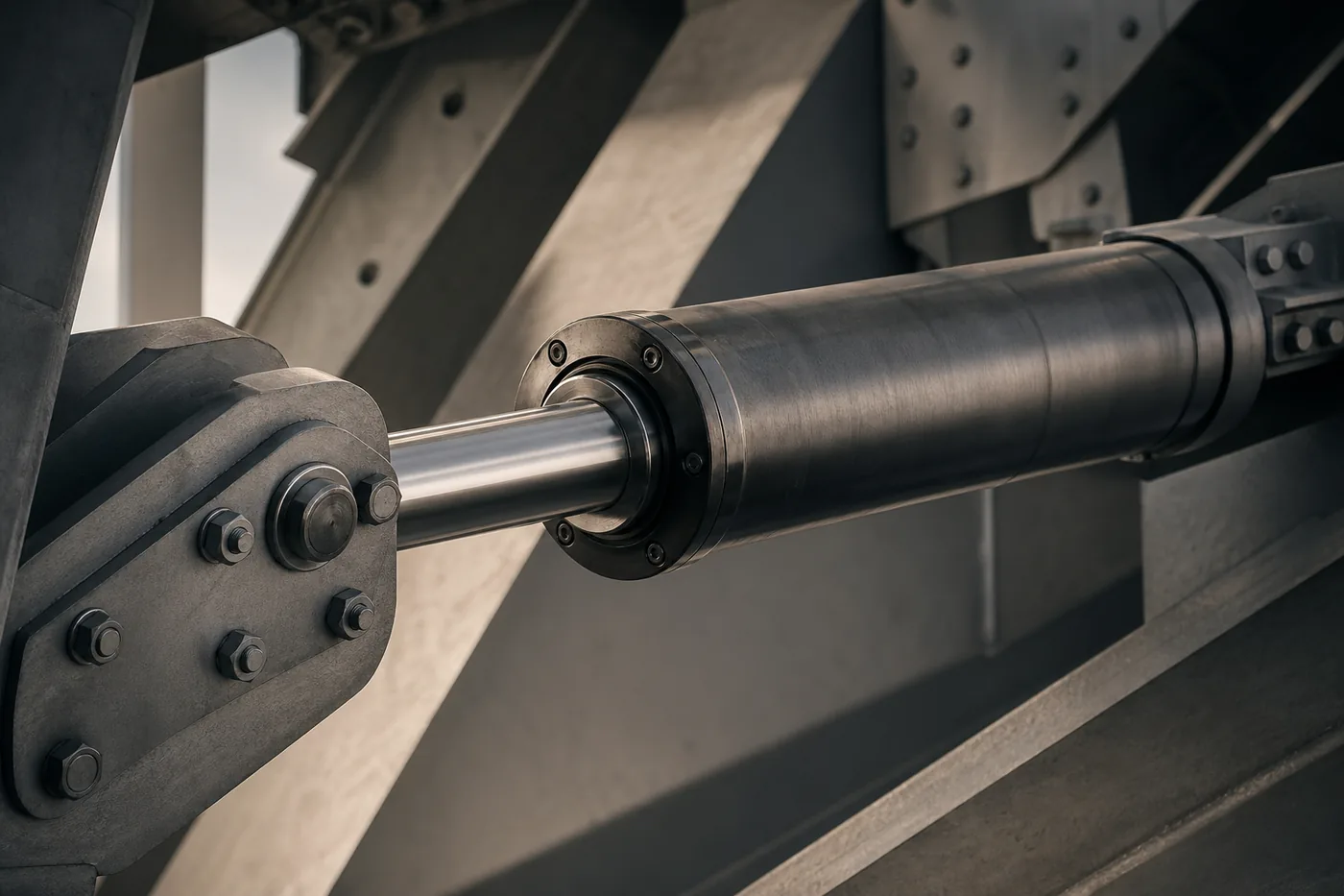
These work by forcing fluid through a piston inside a cylindrical body. The force is proportional not to displacement but to velocity; for this reason, they add damping without significantly increasing the lateral stiffness of the structure. Because they do not shift the period, they preserve modal behavior.
Friction dampers
They absorb energy through the controlled sliding of pre-compressed surfaces. They behave rigidly up to a defined threshold force, then slide once that threshold is exceeded — producing a broad hysteretic loop close to a rectangle.
Metallic yielding devices
These use the yielding capacity of mild steel. They are economical and predictable, but may require replacement after large cycles. They operate in a displacement-dependent manner.
Comparison · summary
- Viscous — dependency
- Velocity (v)
- Friction — dependency
- Displacement (Δ)
- Metallic yielding — dependency
- Displacement (Δ)
- Effect on stiffness
- Viscous: low
- Post-cycle maintenance
- Metallic: possible replacement
03 Selection axes
Device selection cannot be reduced to a single “best” answer; it is evaluated along three axes. The sequence below reflects the control logic ProYA uses at the start of a project:
- Performance target. Uninterrupted use or life safety? As the target rises, velocity-dependent (viscous) solutions come to the fore.
- Structural period. If you do not want to shift the period, use viscous devices; if added stiffness is also needed, use displacement-dependent devices.
- Operation and maintenance. Post-earthquake access, replacement, and cost become decisive in critical structures.
04 Placement and distribution
Selecting the right device is not enough; where and how many devices are installed matters just as much. Efficiency increases when dampers are concentrated on the stories where relative story drift is highest. The choice between diagonal, chevron, and wall–piston layouts is evaluated together with architectural constraints.
In preliminary sizing, we express the target for added damping through the equivalent viscous damping ratio as follows:
# Equivalent viscous damping — preliminary estimate
ξ_eff = ξ_inherent + ξ_added
ξ_added = Σ(Wd,j) / (4π · Ws)

# Wd,j : energy absorbed per cycle by device j
# Ws   : elastic strain energy of the structure
05 Verification: NLTHA
Preliminary sizing is a starting point; the final decision is verified through nonlinear time-history analysis (NLTHA). At this stage, record set selection, scaling, and the realism of the device hysteretic model directly affect the result. We discuss record set setup in detail in record set selection for NLTHA.
In a model with dampers, two outputs in particular are monitored: the device force–displacement loop should fill the expected envelope, and story drifts should remain below the target limit. If both are not achieved, the typical intervention is to revisit the device placement, not the device count.
06 Practical summary
The damping decision is, from start to finish, a discussion of the performance target. The device family is determined by whether the target requires velocity-based or displacement-based control; placement is refined according to the distribution of drifts; final validity is proven through NLTHA.